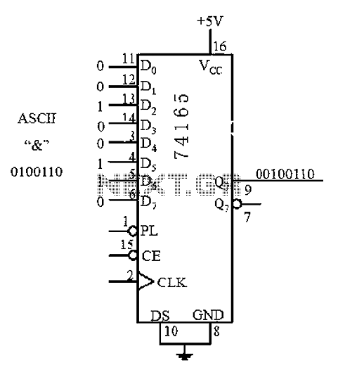
8 BIT PARALLEL TO SERIAL CONVERTER CIRCUIT DIAGRAM SERIAL
In the case of 8-bit data at parallel input, the parallel data will have preference over serial input and serial data will be shift after the parallel data.These pins are total 9 in number and 8 of them are for parallel input, the last one is used for serial input. Now let’s take a look at data input pins.The last control pin, load/Shift is used to enable the data to shift from input pins to the internal flipflops to shift it with each clock pulse. In the case of an active clear state, the data of control pins will also be clear. The clear pin (9) will clear all the data from an output pin and internal flipflops, it will act on logical input LOW. In the remaining control pin, the clear pin will be used to clear the data internally and externally. If the CLOCK INHIBIT pin is active then the clock pulse will be able to move towards the flip flops otherwise it will have no effect on the IC. In the first two pins (7,6), one is used to give the clock pulse to the internal flip flops of the IC and the other pin CLOCK INHIBIT is used to control the clock pulse. The final circuit of the 74LS166 has 16 pins, which includes 4 control pins in the IC. IC 74LS166 is made of 77 different kinds of gates, in which some are used as the inverter and some are used as flip flop too.

VCC Pin 16 Pin 16 is a power input pin for the IC to make it functional. SHIFT/LOAD Pin 15 Pin 15 is an enable pin of the IC, after activating the enable pin the parallel 8-bit parallel and serial input will be a shift with according to each clock pulse. H Pin 14 Pin 14 is used by the LSB of the 8-bit parallel data. F Pin 11 G Pin 12 SERIAL OUT Pin 13 Pin 13 is a serial output pin used to receive the converted 8 bit parallel data in a serial form. E Pin 10 After Pin 2 to 5, Pin 10 to 12 are used to give the remaining 3 -bits of the 8-bit parallel data as an input. CLEAR Pin 9 Pin 9 is a clear pin used to reset the output data and all internally stored data. GND Pin 8 Pin 8 is a ground pin used as common ground by IC with power supply, receiver and sender device. CLOCK Pin 7 Pin 7 is a clock pulse input pin used to change the state of the IC with respect to time. B Pin 3 C Pin 4 D Pin 5 CLOCK INHIBIT Pin 6 Pin 6 is a clock inhibit pin it is used to control the clock pulse signal. A Pin 2 Pin 2 to Pin 5 are the input pins, which are used to input the first 4 bits of 8-bits parallel data. The controller needs a 4 MHz ceramic resonator, X1.PINS DETAIL SERIAL IN Pin 1 Pin 1 is a serial input pin used to input the serial data to the IC. If there is a delay on the Centronics port, the RS232 bitstream from the computer may be stopped via the Flow signal (pin 17).

The IC also generates the requisite control signals. This is essentially a programmed PIC controller that produces a Centronics compatible signal from a 2400 baud serial signal (eight data bits, no parity, one stop bit). The serial-to-parallel conversion is effected by IC1. This is an integrated level converter that transforms the single +5V supply into a symmetrical ☑2V one. Since the computer needs real RS232 levels, an adaptation from TTL to RS232 is provided in the converter by a MAX232. The CTS and DSR signals enable handshaking to be implemented. The TxD line, pin 3, CTS line, pin 8 and the DSR line, pin 6, of the serial port are used - see diagram. It converts a serial 2400 baud signal into a parallel signal. This converter may help if just the serial port on a personal computer is free, whereas the printer needs a parallel (Centronics) port.


 0 kommentar(er)
